
Piecing together the hardware

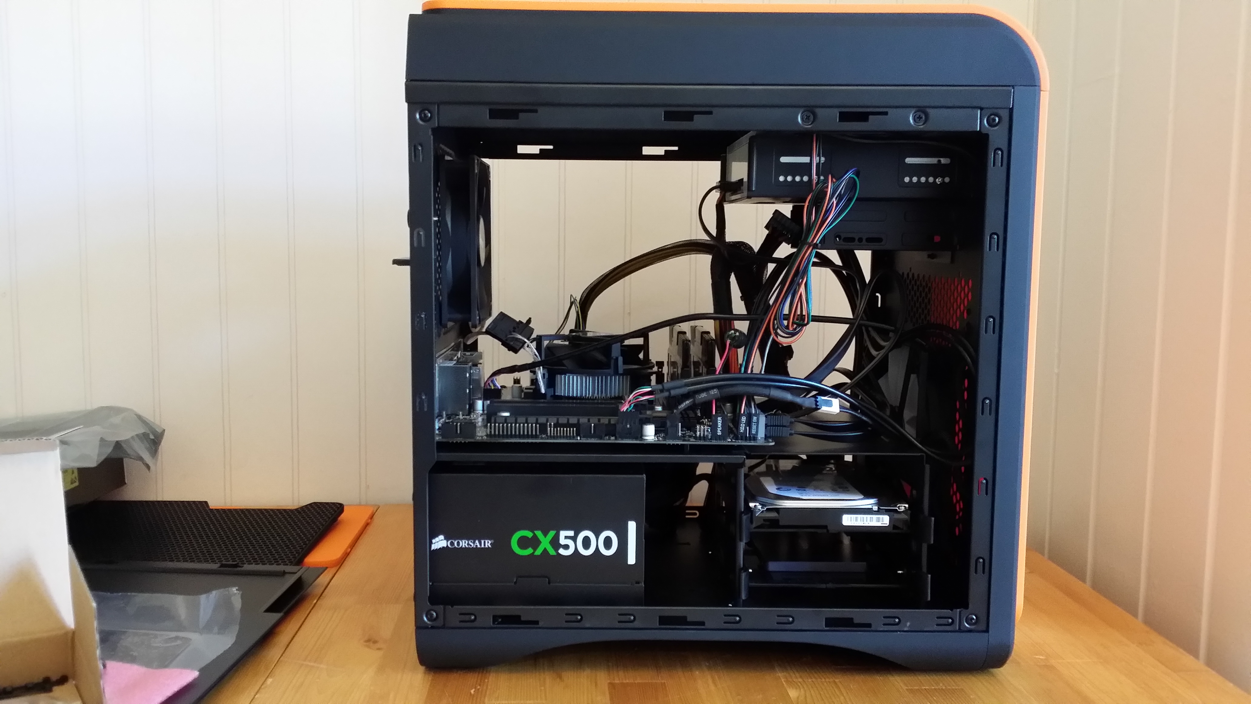
The chassis with the left, right and top access panels removed.
Once upon a time, I bought all my computers in parts and built them myself, but it’s been many years since the last time I did that. Still, how difficult can it be? ![]()
A good place to start is to unpack the chassis and remove the panels (right, left and top in this case) for access.
Tasks
This is just a list of what we will be doing here.
You don’t need to do this in the specified order, but it has its advantages. For example, mounting the PSU first will give you all the power cables so that you can decide if you need to draw a cable through some special crevice while mounting the rest of the components. Mounting the PSU last might force you to make ugly workarounds with the cables if you don’t want to remove some components again. Similarly, waiting to draw all the cables until all the components have been installed will give you more space for the installations.
- Mount the PSU (Power Supply Unit) in the chassis.
- Mount the motherboard in the chassis.
- Mount the CPU with fan on the motherboard.
- Mount the memory cards on the motherboard.
- Mount the system and data drives in the chassis.
- Mount the optical drive in the chassis.
- Draw all the cables.
NOTE: I’ve had trouble before when installing Ubuntu on a system with more than one hard drive. That’s probably only due to my lacking experience with Linux, but I still want to install Ubuntu on the system drive before I mount the data drive. More about that later.
Tools and stuff that you will need
- A Phillips screwdriver #0.
- A Phillips screwdriver #2.
- A SATA control cable for the DVD writer.
The only tool you will need is a Phillips screwdriver. Well, I used two; One #0 for all the internal screws, and one unlabeled (I’m guesstimating that it’s a #2) for the bigger external screws.
All screws and other stuff that you need is provided in the packaging, with one exception; There were two SATA control cables included with the chassis, but with my two hard drives plus the DVD writer, I needed three. I found an old one in a box in my cupboard, probably from before SATA-3 was invented, but it’s good enough for the DVD writer.
It is, of course, unlikely that you have exactly the same components as I do. So I cannot really say anything for sure about what you will need in the form of cables and such…
Oh, and if your eye-sight is fading like mine, I strongly recommend a head-lamp ![]()
Mount the PSU in the chassis
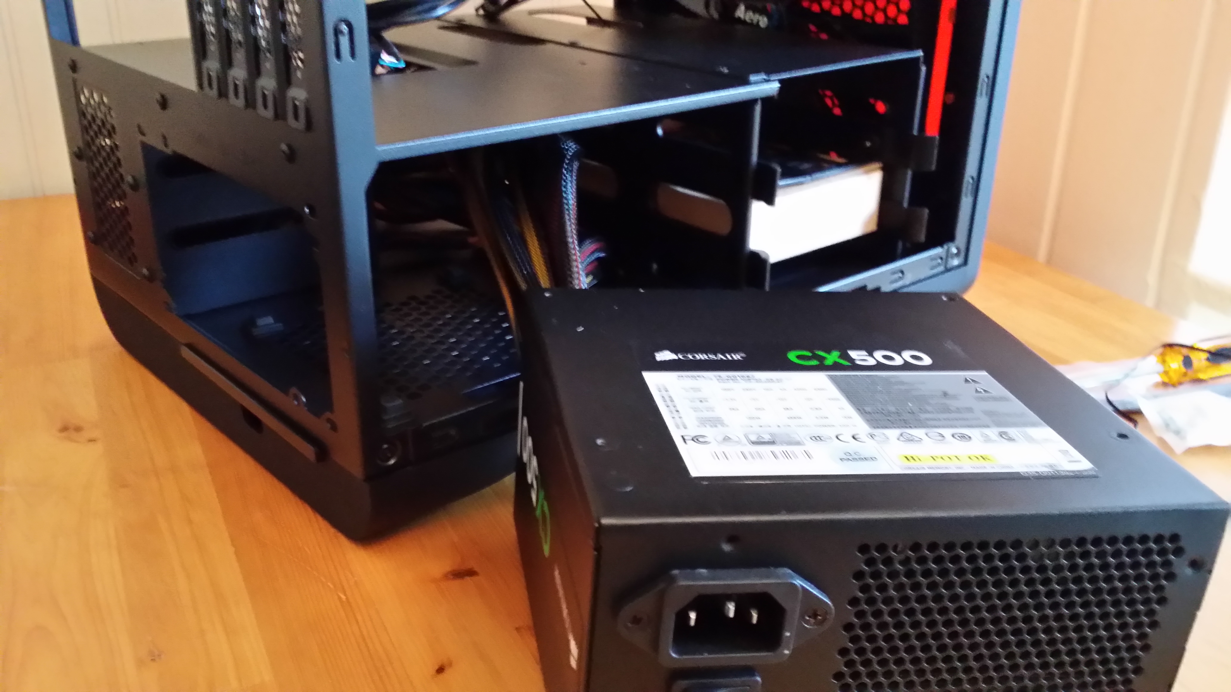
The PSU with the cable bundle drawn through the chassis.
This is one of the easier tasks. The picture to the left attempts to illustrate two points:
- Start by pulling through the cable bundle from the PSU to the other side of the chassis. That’s where you will need them, and doing this after screwing the PSU in place might be a bit of a tight squeeze.
- You don’t see the PSU fan in the picture. That’s because its at the bottom side, which is as it should. The reason is that this is where the chassis have the corresponding air intake.
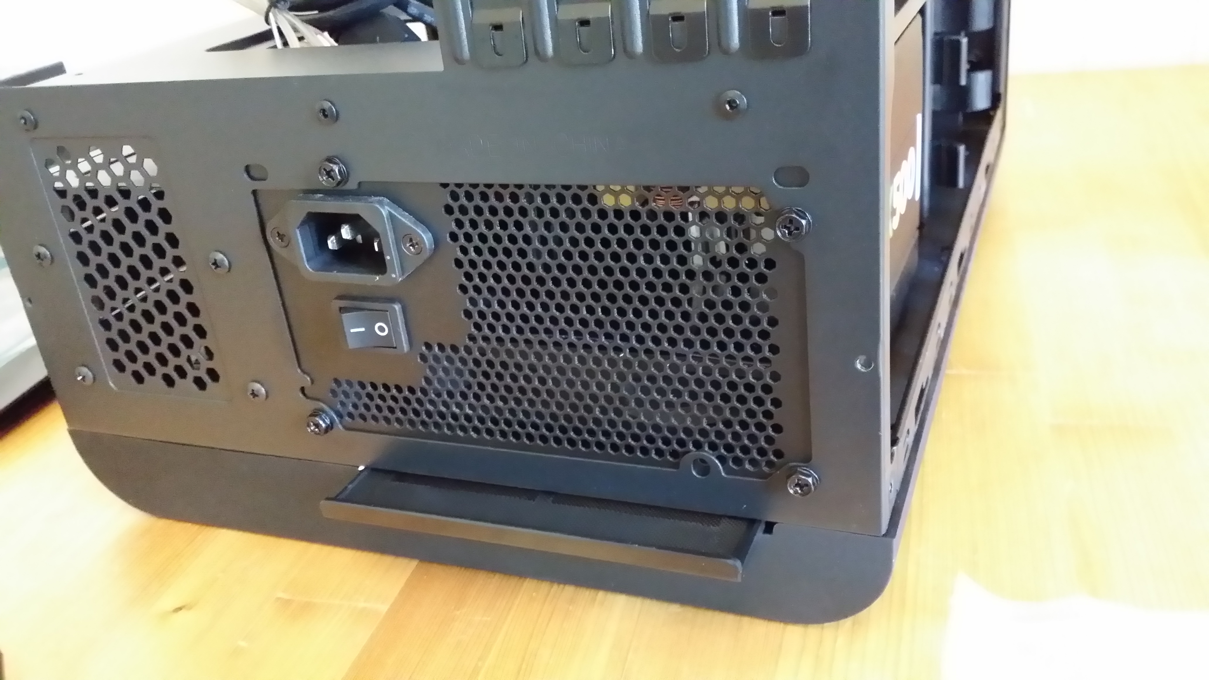
Lower part of the back panel with the PSU screwed into place.
The picture to the right shows the lower part of the chassis’ back panel when the PSU is screwed into place. Note that I’ve pulled out the air-filter just a couple of centimeters to once again say that the PSU fan (I guess I should say the air intake since you might have a PSU with the fan in the other end – pulling air through the PSU rather than pushing it through) should now be at the bottom of the PSU.
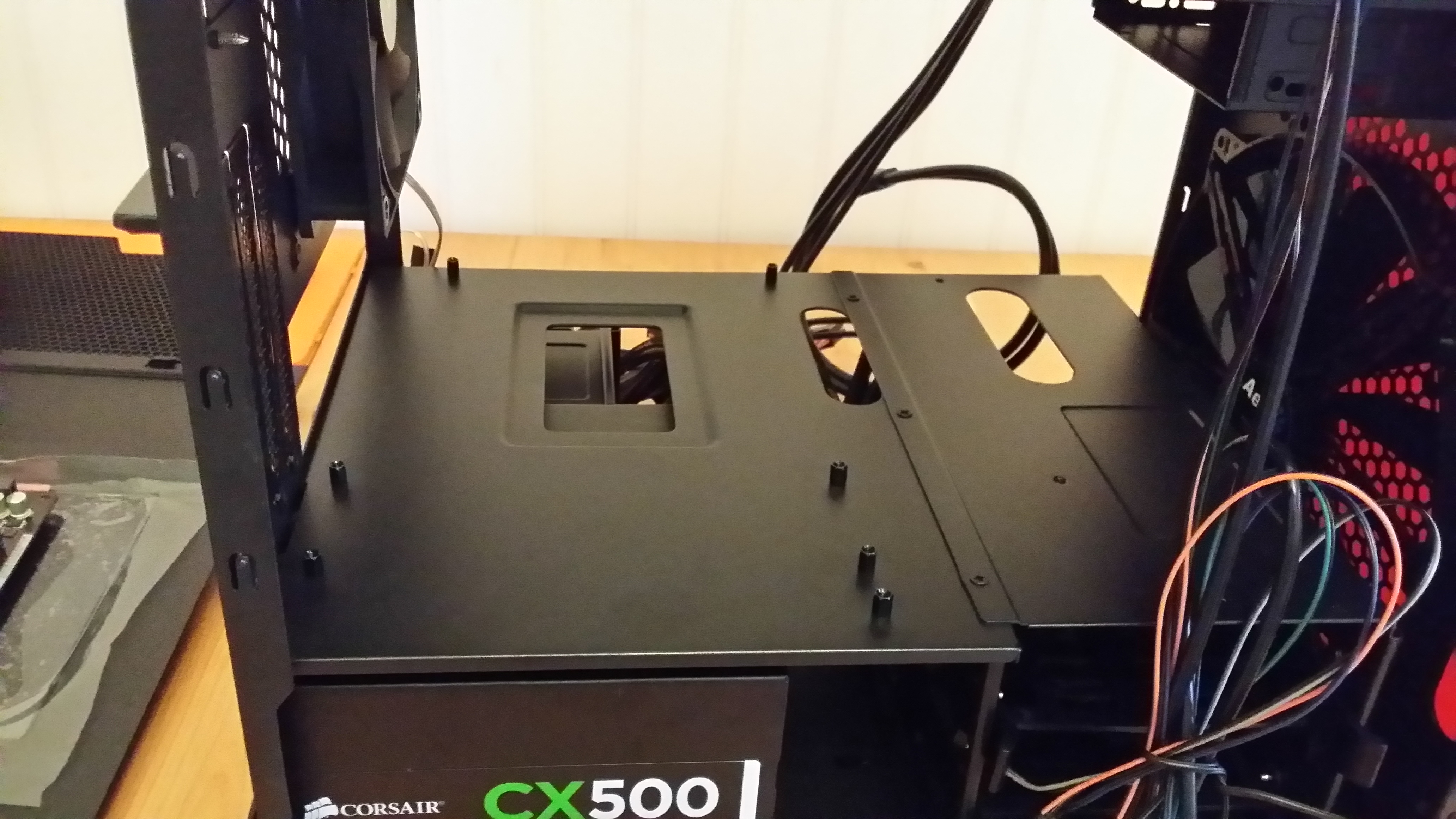
Mount the motherboard in the chassis
First, I feel that I need to say this: There are some pretty sensitive stuff on the motherboard. Unless you have done things like this before and really know what you are doing, you really should read all the safety instructions that came with the components before continuing. What I’m really saying is: Don’t try to blame me if you break anything by your own stupidity (i.e. by not following the safety instructions).
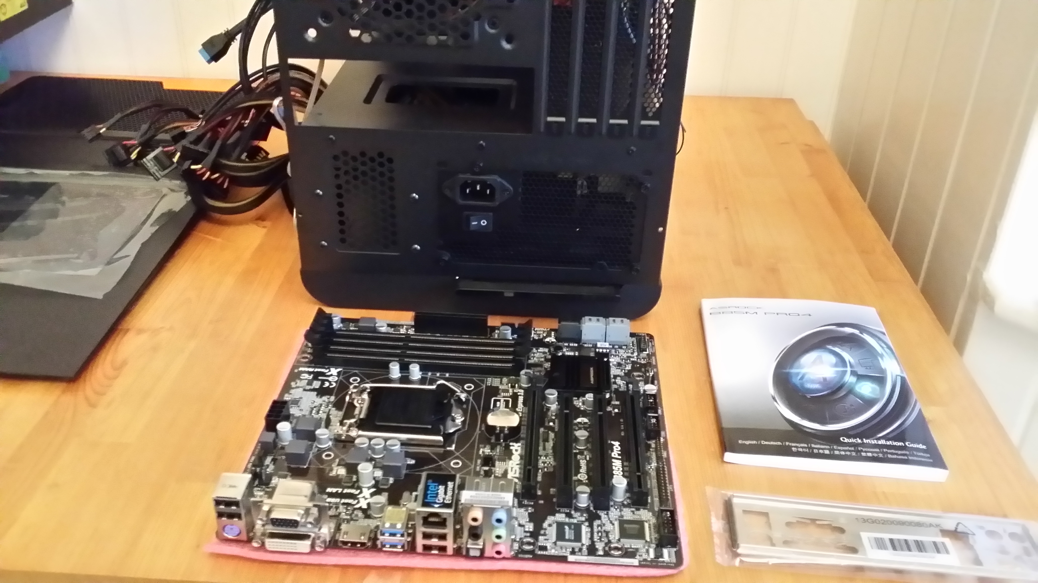
The motherboard at the backside of the chassis. This is the orientation in which it will be mounted, with the I/O panel shield (on the right) in the large slot in the chassis, and the connectors on the motherboard accessible through it.

The I/O panel shield in place.
You should start by putting the I/O panel shield in place (since that will be impossible after you have screwed the motherboard in place). This is the metal plate that sits in the back panel of the chassis where the connectors on the motherboard are. You should have gotten this with the motherboard, since they differ between each motherboard model. The picture to the right shows my shield in place.
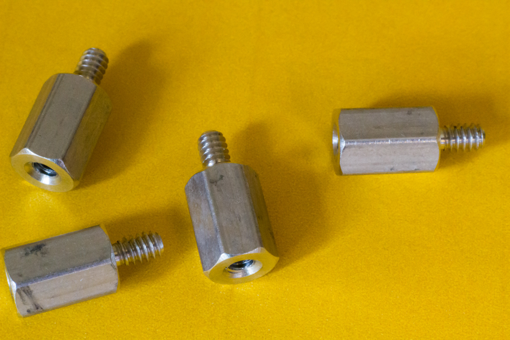
This is what a “standoff” looks like.
The motherboard cannot rest directly on the plating of the chassis – the air flow would not be sufficient for cooling it, and it would also probably short-circuit. So before putting it in place, you need to find your standoffs (see the picture to the left) and screw them into place in the chassis. My motherboard didn’t come with any of the necessary screws or standoffs, but fortunately, the chassis came with a whole box of such stuff – neatly packaged in tiny, labeled plastic bags.
The standoffs on place.
If you compare the layout of your motherboard with the screw holes in the chassis plating where the motherboard will sit, you will probably find that there are one or more holes in the chassis that doesn’t have a corresponding hole in the motherboard, and vice versa. That doesn’t matter. Just put a standoff in each hole in the chassis that has a corresponding hole in the motherboard and leave the rest alone. I ended up using seven standoffs, but one of them (the second closest on the right in the picture) I only added for support – there is no corresponding hole in the motherboard (but nothing on the board to damage or short-circuit either).
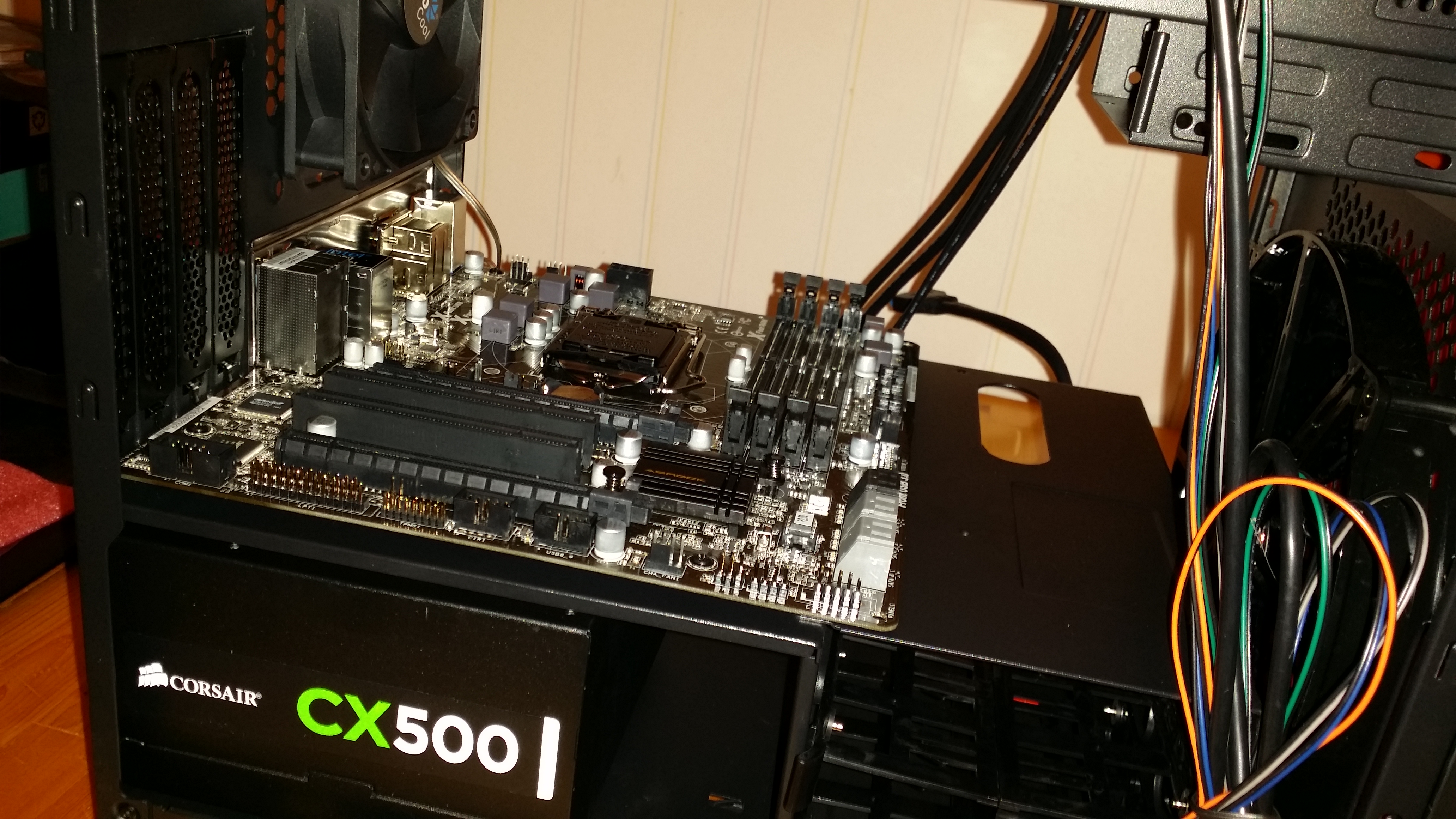
The motherboard screwed into place.
Now it’s time to put the motherboard in place. Use the standoffs as guiding assistance for how to place it. You may find it a bit tricky to get the connectors to align with the holes in the I/O panel shield, but I’m sure you’ll make it. Then screw down the motherboard.
Tip: Before placing the motherboard in the chassis, lay out the same number of screws for use as you have used standoffs.
Mount the CPU with fan on the motherboard
My first reaction when I did this was Wow! How much easier this part has become since I last did it!

CPU with fan mounted on the motherboard.
Just follow the instructions that you got with the CPU to install it and the CPU fan on the motherboard. I cannot really improve on that instruction, and copying them here seems pointless. Well, I can add one thing: When you install the CPU fan; Make sure to set it down in a direction where the CPU fan power cord can reach the corresponding connector on the motherboard.
If you prefer to watch a video with the instructions, click here for Intel’s own video for Socket 1150 CPU installation.
Mount the memory cards on the motherboard
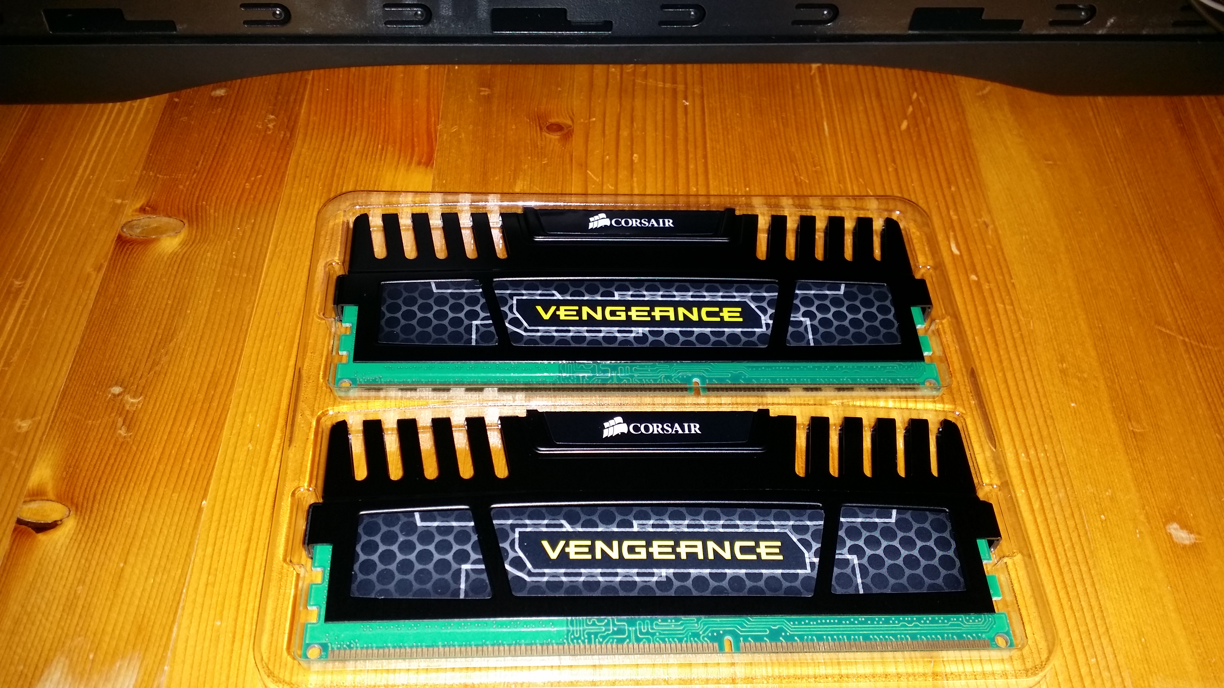
Cool look and cool name. RAM cards are very different nowadays…
Another Wow! Do all memory cards look this cool nowadays? Back in my days they were just scrawny circuit boards with all the circuits exposed. How long has it been again? Better not think about it…
Anyway, the sockets are pretty much the same as earlier. The card only fits one way. Open the locks on either side of the slot by pulling them outwards, align the card over the slot and press downward till you feel it click in place. Don’t press too hard though – if you feel the need to, the card is most likely not aligned correctly. Also, you can try fiddling with the locks while pressing on the card to see if that makes it go smoother.
The reason for why I bought two 4GB cards instead of one 8GB card, is that I want to take advantage of the Dual Channel capability of the motherboard. If your motherboard supports Dual Channel, and has more than two memory slots (as this one do), you need to check the motherboard manual to determine which slots to use. If you use the wrong slots, you will probably be able to access all of the installed memory anyway, but you will not get the increase in speed.
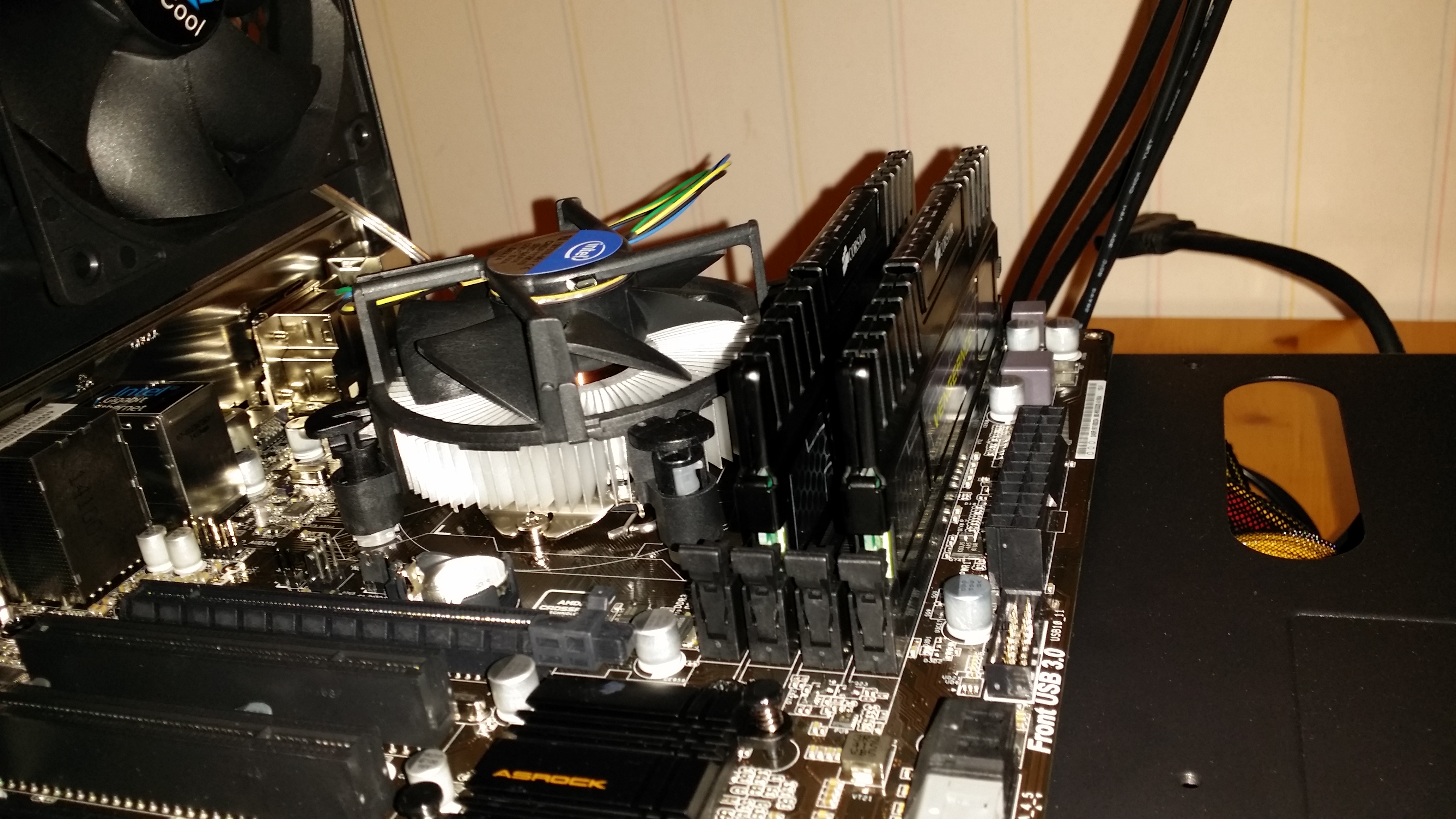
The two memory cards installed next to the CPU.
This motherboard has four memory slots, and I have two identical memory cards. If we name the slots 1 to 4 (left to right, or right to left, doesn’t matter), the cards must be installed in slot 1 and 3, or in slot 2 and 4 – otherwise Dual Channel access will be disabled.
As you can see in the picture to the right, I picked the slots farthest from the CPU (I don’t recall their actual labels) with one empty slot in-between in accordance with above. I don’t imagine having a problem with overheating, but both the CPU and the memory cards give off quite a lot of heat, so that’s why I wanted to separate them as much as I could.
Mount the system and data drives in the chassis
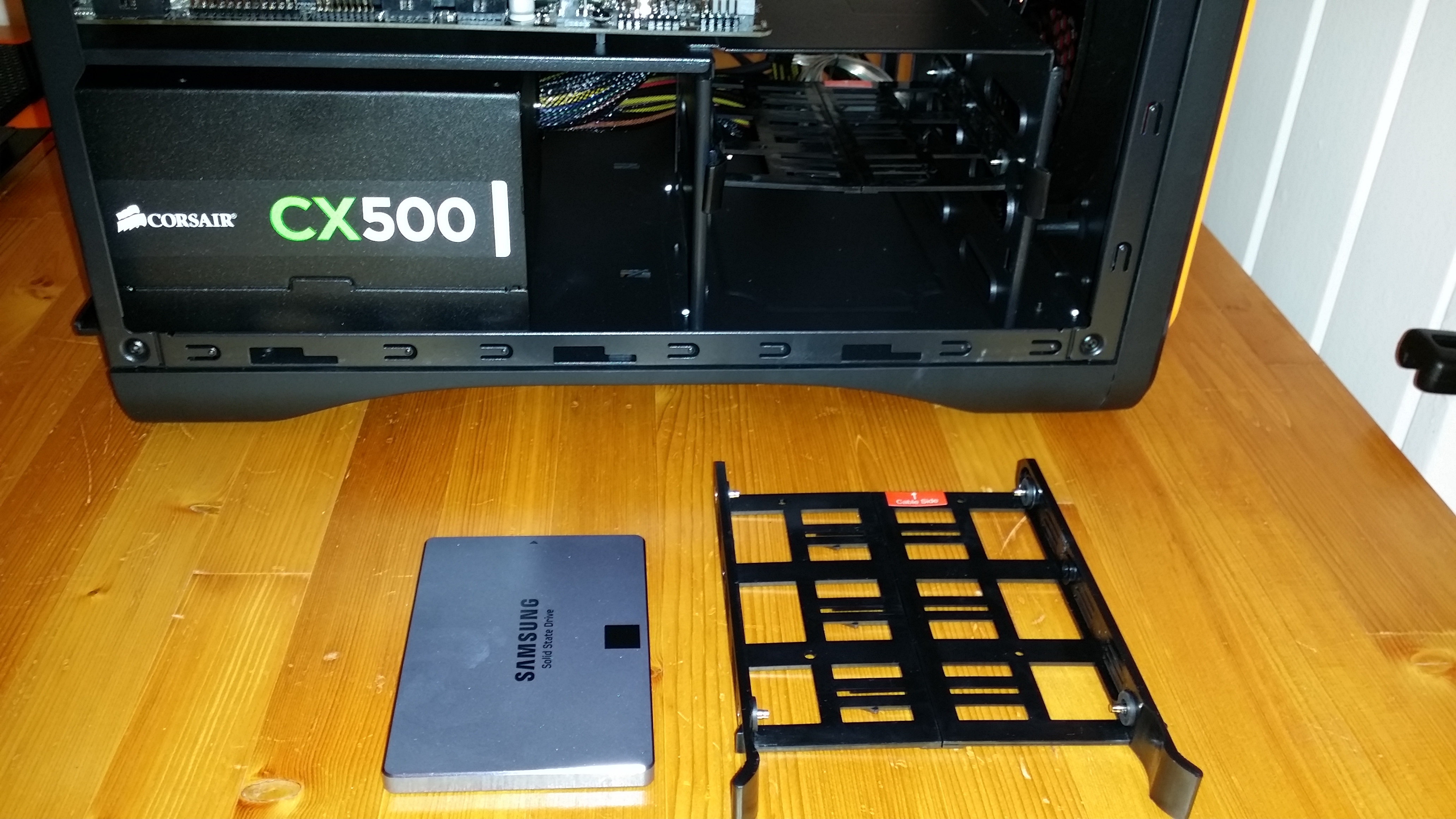
The SSD with cradle below its slot in the drive rack.
The chassis has a rather nice mechanism for mounting drives. Well, there are two actually, one rack at the PSU side for two 3.5″ or 2.5″ drives, and one rack on the other side for 2.5″ drives. I have a 2.5″ SSD system drive and a 3.5″ HDD data drive, and I’ll put them both in the PSU side rack. Partly because that rack is easier to work with, and partly because I’ll use the other rack for another kind of storage by cramming all the unused power cables into it.
The rack has two cradles for drives. I put the system drive in the bottom one, but that’s of no consequence – they are identical.
The picture above shows the SSD that will become the system drive, and to the right of it is the cradle (pulled out from the rack beyond it) on which it will be mounted. The cradle has screw holes that corresponds with the holes in the bottom of the drive, so just screw it in place with the power and data connector facing the other side of the chassis (where the power cables are now). Then slide the cradle back into place in the rack.
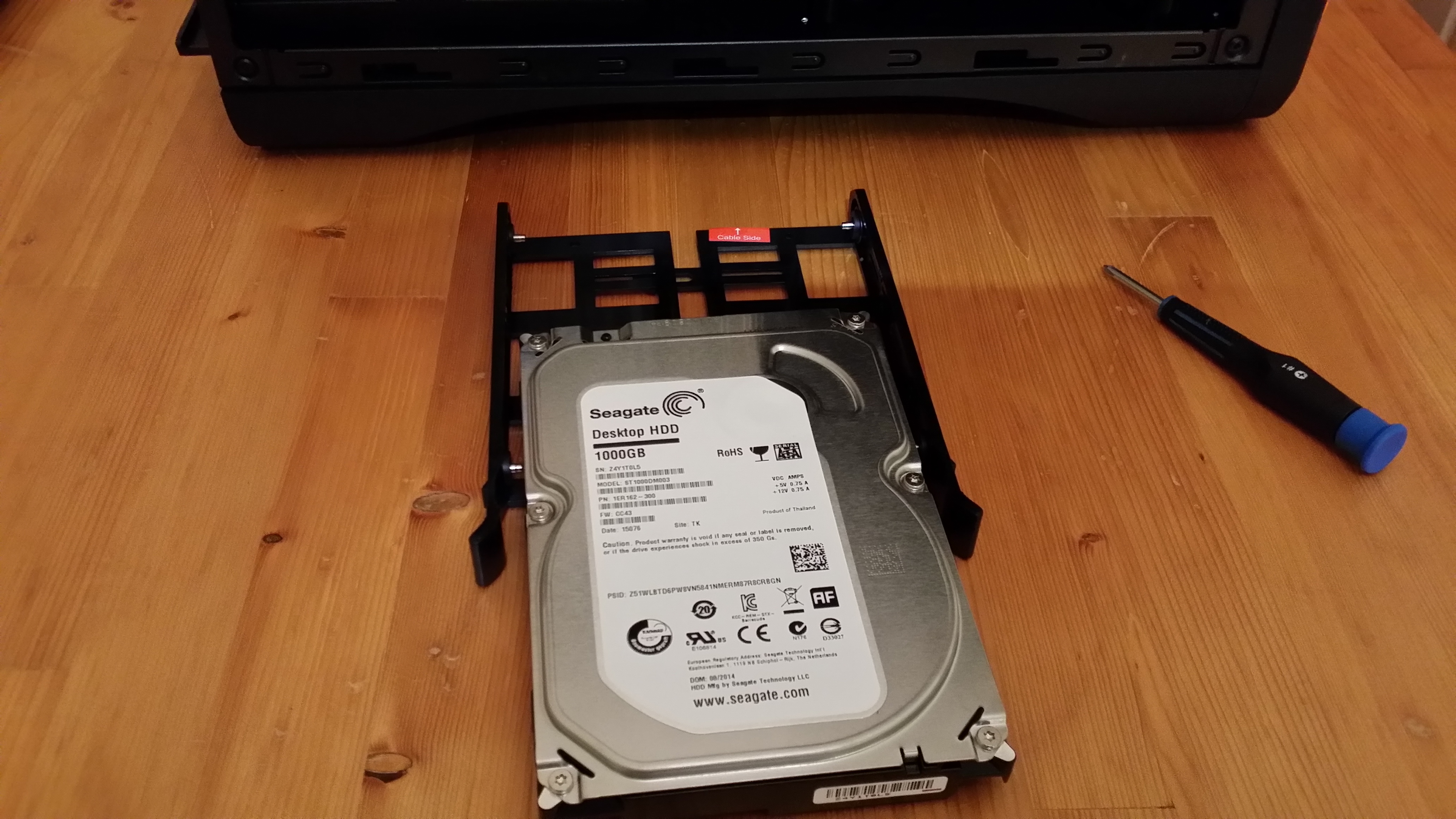
The HDD halfway into its cradle.
Mounting the 3.5″ HDD is even easier. Pull out its empty cradle from the rack and you will notice that the cradle can be pulled apart slightly to allow you to slide the HDD in there. You won’t need any screws for this one since the cradle have four pins that go into the screw holes in the sides of the HDD.
Align the screw holes with the pins (as with the SDD, you want the connectors on the HDD to face the other side of the chassis), and press the cradle back into its original form. Slide the cradle back into the rack, and the HDD will sit firmly locked into place.
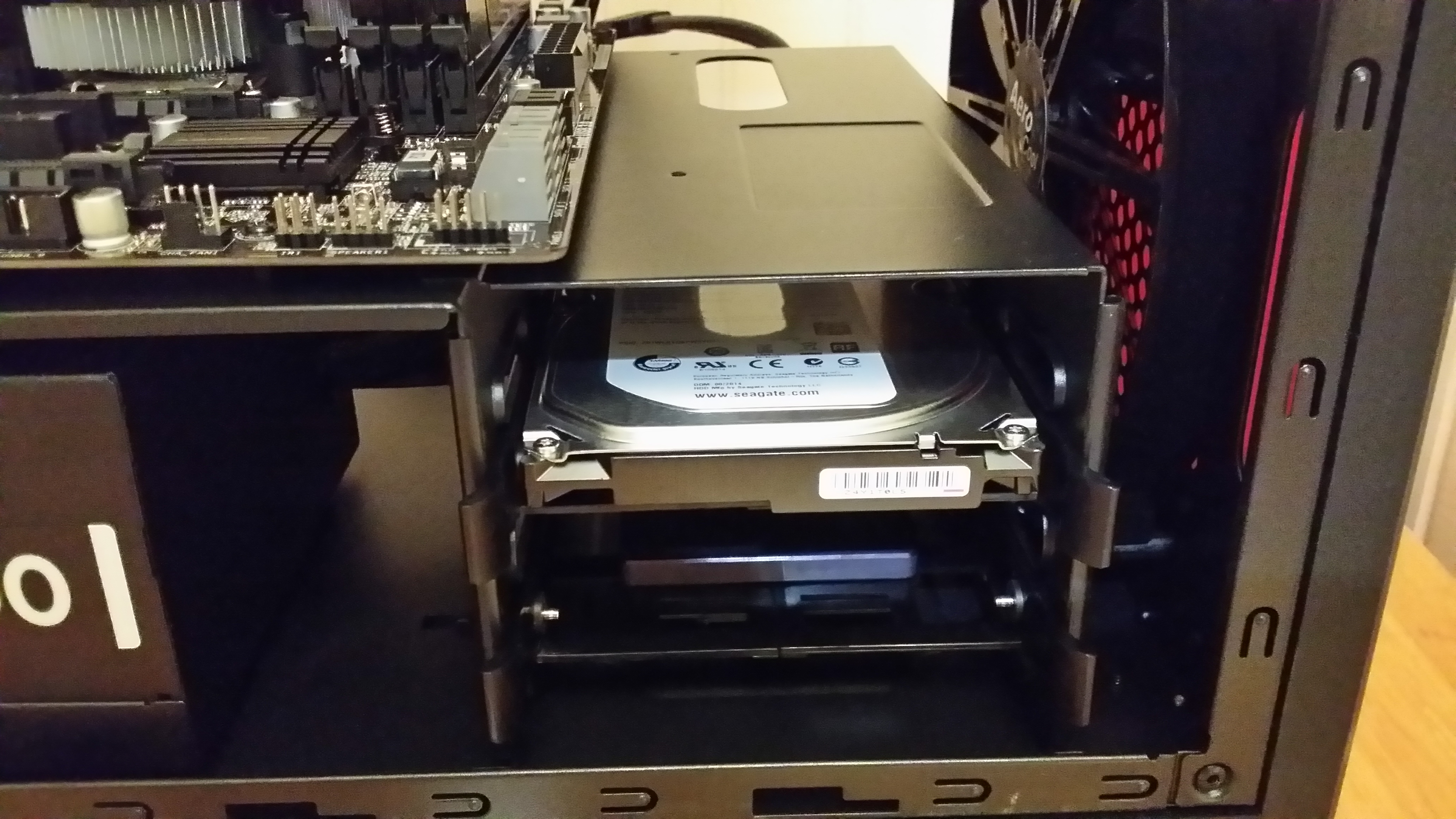
The drives mounted in the rack.
This picture shows both the drives mounted on their cradles in the rack.
Mount the optical drive in the chassis
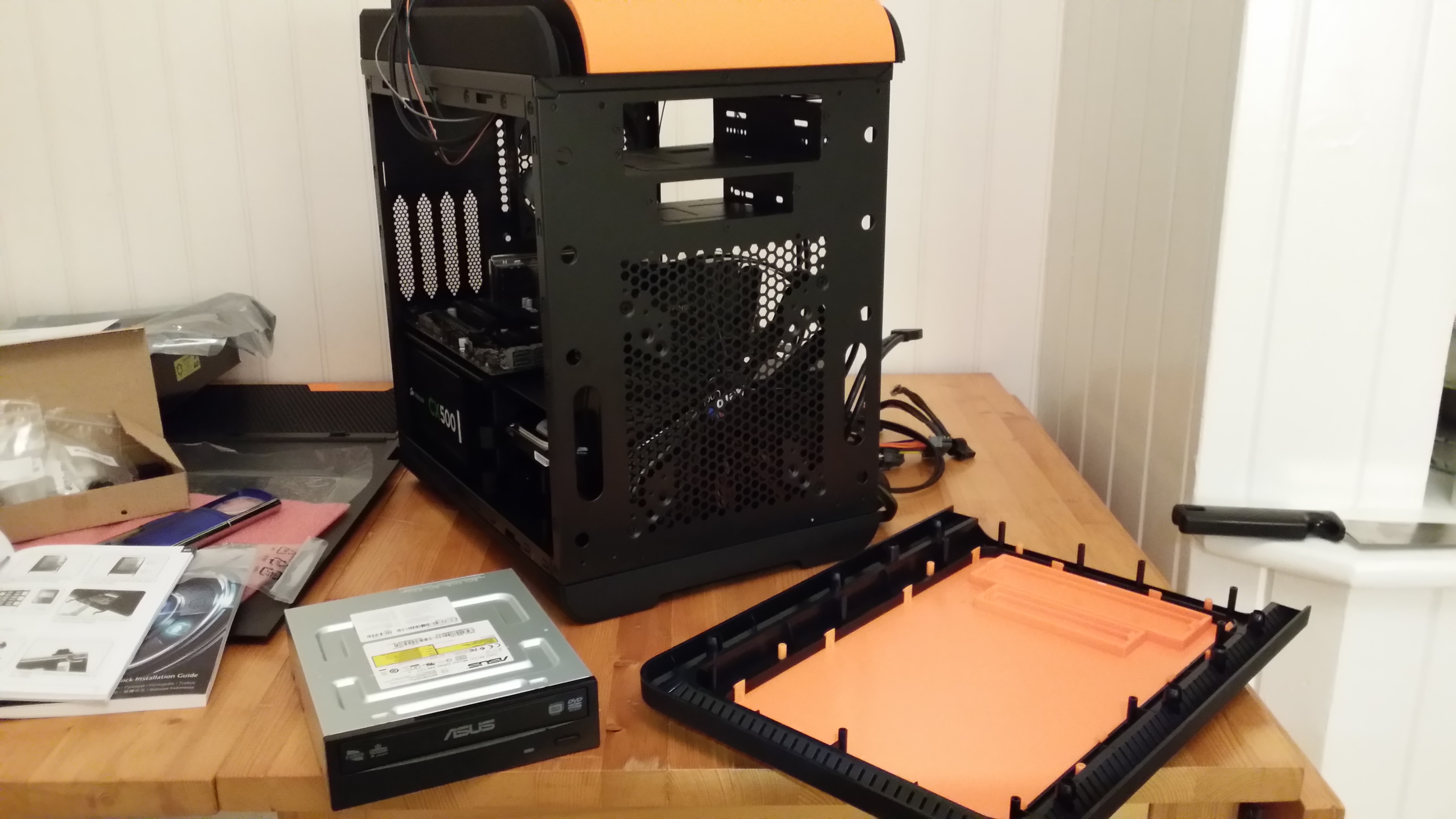
The front panel removed.
It actually took me a couple of minutes to remove the front panel. The reason was that I couldn’t really see which part of it that I was supposed to remove. Hopefully, the picture here with the panel removed will clarify that for you. Just grab the bottom part of the panel and yank it free.
The DVD goes into the top 5″ slot (where else?), so you can start by removing the corresponding cover from the now separated front panel.
Aligning the optical drive with the front panel.
Then you just slide the DVD-writer into place from the outside, and put back the front panel. That may be easier with the drive fastened a bit (this picture should give you an idea of how far in you want to slide the drive), but there’s no point in fastening it completely before the panel is in place so that you can align the front of the drive with the panel.
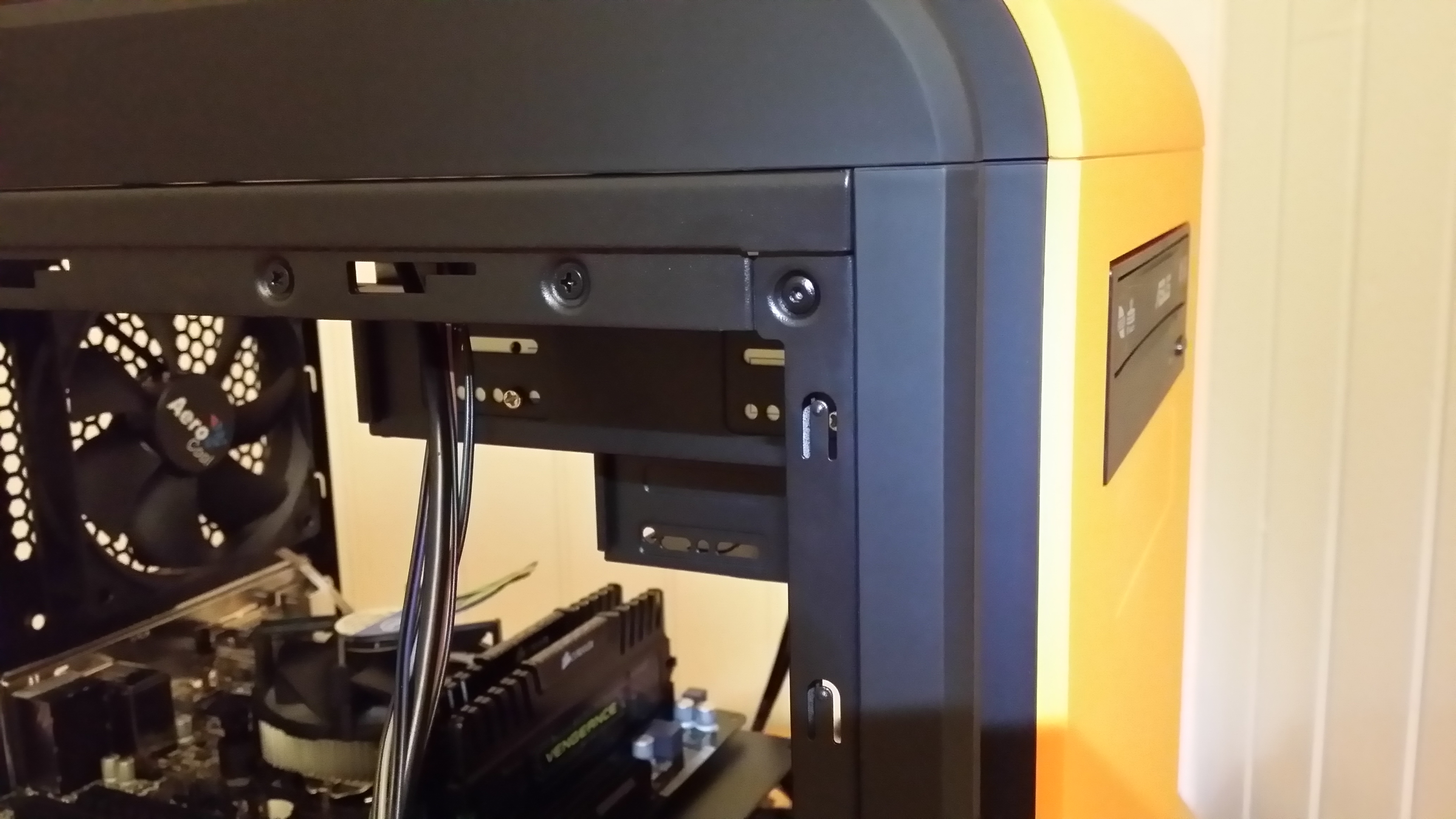
Draw all the cables
All cables drawn and bunted. From the PSU side…
What we have left to do now is to connect all the cables in the chassis. I usually love puzzles of all types, but this is still far from my favorite part.
Some cables are relatively easy to fit, such as the SATA cables. The purpose and placement of others are less obvious. The difficult ones (at least for me) are typically the stuff that connects the chassis to the motherboard. I prefer to start there since it often comes down to a bit of detective work to determine which cable goes into which connector on the motherboard (and in which direction), and it’s easier to do that if you don’t already have jungle of cables crisscrossing the space.
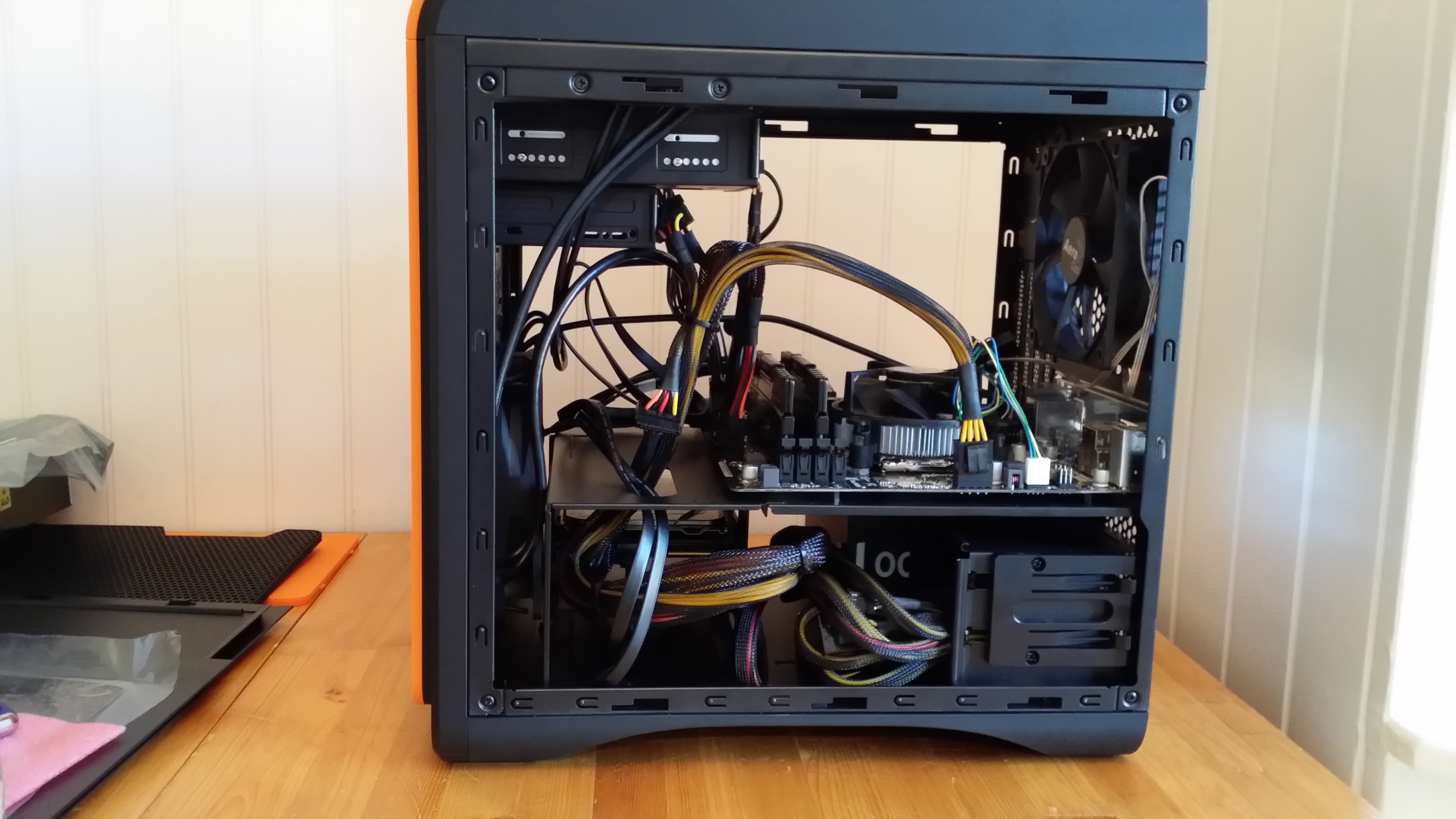
…and from the other side.
Also, try to be smart about the order in which you connect the cables. If you find that connecting one cable will make it harder to reach a yet unused connector, save that one for later.
Cables to connect (so you don’t forget one):
- Power cables (from the PSU):
- 24-pin (12×2) ATX to motherboard.
- 8-pin (4×2) ATX 12V to motherboard.
- SATA power to system drive (the SSD).
- SATA power to data drive (the HDD).
- SATA power to optical drive.
- The fans (they get power from the motherboard connector, so don’t connect any separate power connectors even if they have those):
- CPU fan to motherboard.
- Front chassis fan to motherboard.
- Rear chassis fan to motherboard.
- SATA control cables. Make sure to use SATA-3 connectors on the motherboard (mine has four SATA-3 and two SATA-2), at least for the system and data drives:
- The system drive (the SSD) to motherboard. Preferably to the first SATA-3 connector, making it the default boot drive.
- The data drive (the HDD) to motherboard. NOTE: See Don’t connect the HDD yet below!
- The optical drive to motherboard. If you intend to add lots of drives, you might want to use one of the (slower) SATA-2 connectors on the motherboard for this one.
- From the chassis itself:
- USB 3 connector to motherboard (to use the external connectors).
- USB 2 connector to motherboard (to use the external connectors).
- Power switch to motherboard.
- Reset switch to motherboard.
- Power LED to motherboard.
- HDD activity LED to motherboard.
- Front panel audio to motherboard. I don’t expect to use it, but connected it rather than having an unused cable hanging around that I’ll probably begin to wonder about in a month or two.
- The tiny speaker that came with the chassis to the motherboard. Might want to skip this if you don’t want the server to wake you up if it feels like rebooting in the wee hours.
I don’t usually bother to bunt the cables together, but I made an exception this time so that the final pictures of the inside here would look as nice as possible. Do as you will with that.
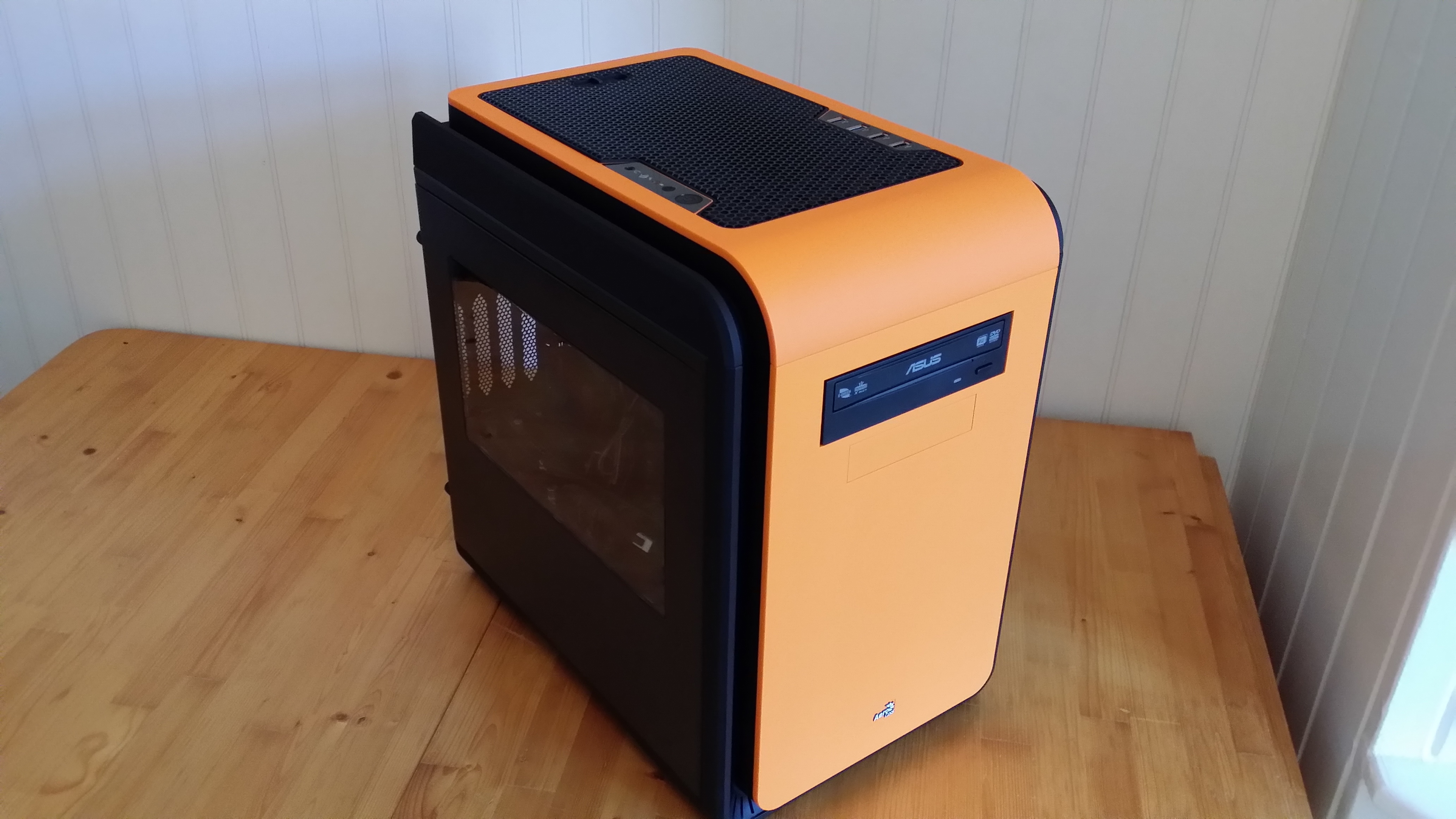
The server all finished up (at least the hardware).
You should probably wait to put the panels into place until you have tested the system (see the next page), and until you have connected the data drive after installing Ubuntu if you chose to do that (see the next section). Still, this picture shows how it looks when it’s finally closed.
Don’t connect the HDD (data drive) yet!
Well, you can obviously do as you please with that, but I waited with connecting the SATA control cable to the data drive (the HDD) til I had installed Ubuntu on the server. The reason is several earlier failed attempts to install Ubuntu on systems with more than one drive attached (during installation that is).
So, if you want to be sure not to have such installation problems, don’t connect the SATA control cable to the HDD at this point. Ill remind you to do it after we have installed the operating system, and show you how to make Ubuntu Server use it properly.
Nice looking stuff there on the bureau. And the bureau itself ain’t looking too bad either. – Ikea, is it?
Thanks, Tobbe. And, yup – Ikea